In inventor fillet command used to add fillets or rounds to one or more edges or faces. Rounds off or caps interior or exterior comers of a component or features of a component. You can create edge, face, or full round fillets.
Where do I find it?
From the 3D modeling ribbon -> modify -> fillet.
![]()
How to use inventor fillet command?
I. Create a constant radius – edge fillet.
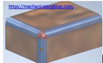
1. Click the fillet icon.
2. In the fillet dialog, select edge fillet, select constant tab and select the edges in the graphics window. Set the radius value and select continuity option.
+ Tangent (G1) fillets which are tangent to adjacent faces.
+ Smooth (G2) fillets which are curvature continuous to adjacent faces.
+ Inverted fillets which are curvature continuous to adjacent faces.
3. In the select mode group:
+ Edge: You can Select or remove single edges.
+ Loop: You can Select or remove the edges of a closed loop on a face.
+ Feature: You can Selects or removes all edges of a feature.
4. In the solid group:
+ All Fillets: Selects or removes all remaining concave edges and corners.
+ All Rounds: Selects or removes all remaining convex edges and corners.
5. Click OK to finish this command.
II. Create a variable – radius edge fillet.

1. Click the fillet icon.
2. In the fillet dialog, select edge fillet, select variable tab and select the edges in the graphics window.
3. In the point list you can select position, radius of start and end point. If you want to add more point, drag the mouse in the edge and left click. You can modify the position and radius in the point list.
4. Click OK to finish this command.
III. Create a fillet between two faces.
1. Click the fillet icon.
2. In the fillet dialog, select face fillet.
3. In the graphics window, select the first face and select second face.
4. Click OK to finish this command.


Leave a Reply