If you are learning mechanical engineering, you must know about gear. In this post, mechanicalengblog.com will introduction spur gear. You will know: What is a spur gear?, Why use spur gears? Limitations of spur gears

I. What is a spur gear?
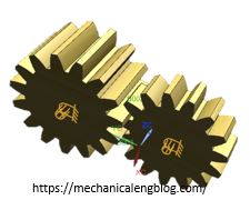
Spur gears are the most common gears founded in motivation between two parallel shafts.It is a type of gear used in various machines and mechanical systems to transfer power from one component to another. It is composed of two or more cylindrical disks with teeth cut into the circumference of the outer edge. The teeth are cut in an involute tooth profile, which helps them mesh together smoothly and efficiently. Since the teeth mesh together parallel to the shaft, no thrust is generated in the axial direction. In addition, due to the ease of manufacture, these gears can be made to a high degree of precision.
The unit of tooth size is called the module. The common pressure angle of spur gears is 20°. In general, this type of gear with the same modulus will engage with each other. However, the tooth profile can change as the center distance between the two axes changes. This helps to minimize grinding which reduces tooth life, noise, vibration or tooth slip due to less contact which maximizes gear transmission.
Straight cylindrical gear size includes Module M1, Module M1.5, Modules M2, Modules M2.5, Modules M3, Modules M4, Modules M5, Modules M6, Modules M8, Module M10.
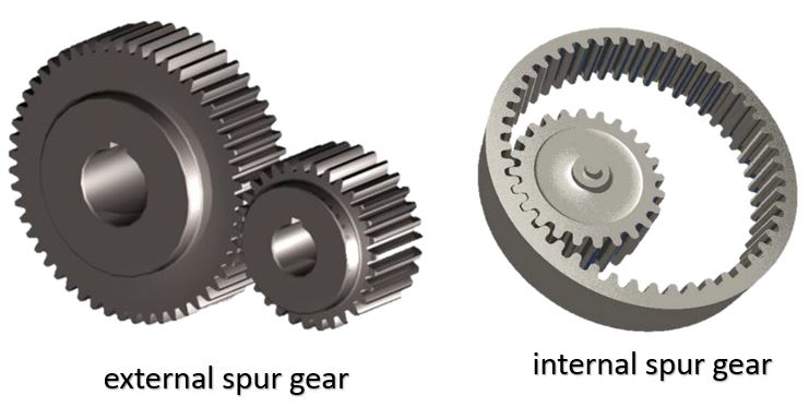
Type of spur gear. There are two type of spur gear: external and internal spur gear.
Terminology of Spur Gear

Top Land: The top most surface of the gear tooth.
Bottom Land: The bottom most surface of the gear tooth.
Pitch Circle: When two gears have meshed together, then the point on which one gear tooth is in contact with the tooth of the other gear is called the contact point. And the imaginary circle that passes through this contact point is called the pitch circle. The speed of the gear is measured here.
Pitch Circle Diameter (PCD) . The diameter of the pitch circle.
Module: A module (m) is defined as the ratio of pitch circle diameter in mm to the total number of teeth.
The formula of the module: m = PCD/n (Pitch circle diameter/number of teeth )
Circular Pitch (Cp)
The distance between a point of the tooth, measured at the same point in the adjacent teeth, is known as the circular pitch along the circumference of the pitch circle.
The formula of the Circular Pitch.
Cp = PCD×π/n
Cp = m×π ( m = PCD/n)
PCD = Pitch circle diameter
N = number of teeth
π = 3.14
m = Module
Addendum (A): The high of teeth where from pitch circle to addendum circle
Since we know that, Addendum is equal to the module. A = m
Addendum Circle: It is the outside circle which surrounds the outer ends of the teeth
In external gears, the addendum circle is on the outer cylinder while in the internal gears the addendum circle is on the inner cylinder.
The diameter of the addendum circle can be calculated by this formula.
Addendum circle diameter = Pitch circle diameter +2Addendum
Clearance (C) . When two gears meshed together, then the gap between the addendum circle of the top tooth and the addendum circle of the other tooth is called the clearance.
The formula of the Clearance.
C = Cp/20 (Cp: Circular Pitch)
Dedendum (D): The distance between the pitch circle and the dedendum circle.
D = A (Addendum)+ Clearance
Dedendum circle (DCD): the root circle which surrounds the bottom of teeth.
The formula of the dedendum circle
DCD = Pitch circle diameter -2× Dedendum
Tooth Thickness(T). Tooth thickness is the distance that is measured along the pitch circle of two attached teeth.
T = Circular Pitch/2
Diametrical Pitch (DP)
Diametric pitch is the number of gear teeth divided by the pitch circle diameter.
DP = n/PCD
DP = 1/m (since, m = PCD/n)
PCD = Pitch circle diameter
n = number of teeth
m = Module
Total Depth: Total depth is the sum of addendum and Dedendum.
TD = Addendum+Dedendum
Pressure angle
The tangent line drawn at the pitch point and the normal line drawn from the same pitch point, the angle it makes from that tangent line is called the pressure angle.
Generally, pressure angle is used up to 20°.
Gear Ratios
A gear ratio of spur gears is defined as it is the ratio of the number of teeth on the driven gear to the number of teeth on the drive gear.
gear ratio = N2/N1
N2 = Number of teeth in the driven gear
N1 = number of teeth in driver gear
II. Why use spur gears?
The first reason is that it is very simple to install the spur gear. Secondly, this type of gear has high power transmission efficiency. Thirdly, people can easily make it, because of this it is quite cheap. Not only that, the straight cylindrical gear also helps to create high precision.
Spur gears are an important type of gear used in many machines and devices. In a typical machine, has a central shaft or axis, while the two gears are attached to the ends of the shaft. The two gears mesh so that when one gear turns, it causes rotation in the other gear.In a typical machine or device with spur gears, there is a central shaft or axis which is turned by one of the spur gear and then transmitted to another one through meshing teeth on each gear.The two spur gears can be connected at either end of their axes.
1. Advantage of spur gear.
+ Simplicity: It has compact size, large power transmission capacity, and making simple process.
+ Reliability: High durability, application in the machine manufacturing industry. Easy to replace as well as to integrate in the machine system.
+ Efficiency: The working efficiency of spur gears is high from 97% to 99%.
+ Constant Speed Drive: The transmission ratio is always unchanged, and combining multiple sets of spur gears produces multiple gear ratios
2. Disadvantage of spur gears
Although these straight cylindrical gears have the machining of straight shaft gears, high precision is required. Requires high-precision manufacturing machinery as well as skilled workers.
Be some strength, they have some remarkable shortcomings. The first shortcoming which makes them become annoying is that they are too noisy when running at high speed. And the second is they are very fragile. Maybe you should buy a stockpile of spur gears to change when needed.
However, these shortcomings cannot negate their high applicability. Spur gears are commonly used in mechanical equipment such as motorcycle gearboxes, lathes, concrete mixers, drills, metal cutters, power plants, marine engines, fuel pumps, and even familiar household appliances such as clocks, washing machines.
III. Spur Gears Applications
+ Spur gear are also used to increase or decrease the speed of an object. It can be used to increase or decrease the torque or power of an object.
+ It is used for transmission and force from one shaft to another in a gas machine structure. For this purpose, Spur gear are used in washing machines, mixers, tumble dryers, construction machines, fuel pumps and factories.
+ In power plants, so-called spur gear “trains” are used to convert a form of energy such as wind energy or water energy into electrical energy.
+ Spur gear are widely used in aircraft, train, bicycle, ball mill and workstation engines where noise is not an issue.
Some typical industrial applications include gear reducers, conveyor systems, reducers, motors, mechanical conveying systems, gear rotary machines, motors and machining tools.


Leave a Reply