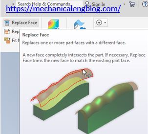
In Autodesk inventor replace face command use to replace one or more part faces with a different face. A new face completely intersects the part. It necessary, replace face trims the new face to match the existing part face. Where do I find it? 3D model -> surface -> replace face. How to use replace […]
Inventor modeling tutorials
Autodesk inventor extend surface command

In Autodesk inventor extend surface command use to make a surface larger on one or more directions by specifying a distance or a rumination plane. In the dialog box, click more to specify which method extends the edges. Extend follows the direction og edges adjacent to the selected edges. Stretch extends the edges in a […]
Autodesk inventor trim surface command
In Autodesk inventor trim surface command use to remove the area of a surface defined by a cutting command. The cutting tool can be as urface quilt, a single part face, a single non-intersecting 2D sketch curve, or a work plane. Trim surface automatically extends a 2D sketching cutting command that does not intersect the […]
Autodesk inventor boundary patch command
In Autodesk inventor boundary patch command use to create a planar or 3D surface within the boundary of a specified closed loop. You can apply contact (G0), tangent (G1), and smooth (G2) boundary conditions to each edge of surface. Where do I find it? 3D model -> surface -> boundary patch. How to use inventor […]
Autodesk inventor ruled surface command
In Autodesk inventor ruled surface command use to create a surface that extends a specified distance and direction from the selected edge. Direction is set automatically by a normal or tangent to face selection. Use vector to set the direction by face, work plane, edge, or axis.
Autodesk inventor stitch surface command

In Autodesk inventor stitch surface command use to join surface together into a quilt or a solid. Surface edges to be joined must be the same size and adjacent to each other. Stitching surfaces that from a closed volume create a solid unless you elect to maintain as a surface.