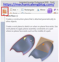
In Autodesk inventor boundary patch command use to create a planar or 3D surface within the boundary of a specified closed loop. You can apply contact (G0), tangent (G1), and smooth (G2) boundary conditions to each edge of surface.
Where do I find it?
3D model -> surface -> boundary patch.
![]()
How to use inventor boundary patch command?
I. Create boundary surface from 2D sketch.
Create a planar or 3D surface from a closed 2D sketch, a closed boundary, or a mixture of both.

1.Click 3D model tab -> surface -> boundary patch icon.
2. In the graphics window, select the profile to create a boundary patch.
3. Click OK to finish this command.
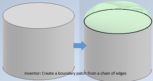
II. Create a boundary patch from a chain of edges.

1. Click 3D model tab -> surface -> boundary patch icon.

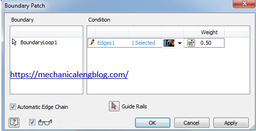
2. In the graphics window, select a chain of tangent or continuous edges that define a closed loop. If you have mistaken and want to remove last selection, right click and select undo last selection.
3. Click the arrow under condition, you can select the boundary surface is tangent, contact, or smooth.
4. Click OK to finish this command.


Leave a Reply