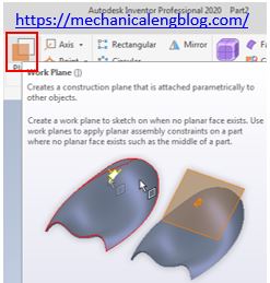
In Autodesk inventor work plane command use to create a construction plane that is attached parametrically to other objects. Create a work plane to sketch on when no planar face exits. Use work planes to apply planar assembly constraints on a part where no planar face exits such as the middle of a part.
Where do I find it?
3D model -> work features -> plane.
How to create new work plane in inventor?
I.Create new plane by offset from a face option.
Create a work plane parallel to a selected face of plane at a specified offset distance.
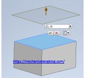
1. Click plane command.
2. Select offset from a face option.
3. In the graphics window, select the face to offset and set the offset value of offset and click apply to create new plane.
4. Click apply to create new plane.
II. Parallel to plane through point option.
Create a work plane parallel to a selected point, face, or plane through a point.
1. Click plane command.
2. Select parallel to plane through point option.
3. In the graphics window, select point and face or plane that you want to make parallel.
III. Midplane between two planes.
Creates a work plane in the middle of two planar faces or planes.
1. Click plane command.
2. Select midplane between two planes option.
3. In the graphics window, select first and second plane that you want to reference.
IV. Midplane of torus.
Creates a work plane through the center, or midplane, or a torus.
1. Click plane command.
2. Select midplane of Torus option.
3. In the graphics window, select a torus that you want to reference.
V. Angle to plane around edge.
Creates an angled work plane around a face or edge.
1. Click plane command.
2. Select angle to plane around edge option.
3. In the graphics window, select a face that you want use for reference and select a part face or plane and any edge or line parallel to the face. Set the angle value in the edit box.
4. Click apply to create new plane.
VI. Three points.
Creates a work plane through three endpoints, midpoints, intersections, or work points.
1. Click plane command.
2. Select three points option.
3. In the graphics window, select first, second, third point to create new plane.
VII. Two coplanar edges.
Creates a work plane through two coplanar work axes, edges, or lines.
1. Click plane command.
2. Select two coplanar edges option.
3. In the graphics window, select first and second coplanar edges to create new plane.
VIII. Tangent to surface through edge.
Creates a work plane through an edge and tangent to a curved surface
IX. Tangent to surface through point.
Creates a work plane through an endpoint, midpoint, or work point and tangent to a curved surface.
X. Tangent to surface and parallel to plane.
Creates a work plane tangent to a curved surface and parallel to a plane.
1. Click plane command.
2. Select tangent to surface and parallel to plane option.
3. In the graphics window, select the surface and plane to create new plane.
XI. Normal to axis through point.
Creates a work plane perpendicular to an edge or work axis and through an endpoint, midpoint, or work point.
XII. Normal to curve at point.
Creates a work plane perpendicular to a curve and through a vertex, edge midpoint, sketch point, or work point.


Leave a Reply