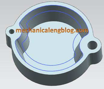
In the Siemens nx modeling, we can create a pocket following: Cylindrical, rectangular, general by pocket command. It uses to remove material from a solid body or modifies a sheet body with faces made by projecting a section along a vector.
This command is active until the Siemens nx 11.
You are reading a guide how to use pocket command in Siemens NX. Click here to read all design feature in Simens NX.
Where do I find it?
From the menu (top border bar): insert -> design feature -> pocket.
From the home tab: feature group -> design feature drop-down -> pocket.
I. Create a cylindrical pocket.
1. From the menu: insert -> design feature -> pocket.
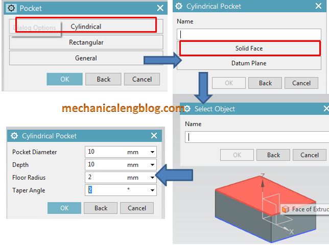
2. In the pocket dialog, we will select cylindrical option.
3. In the cylindrical pocket dialog, you can select solid face, or datum plane option. For this tutorial, I will select solid face option.
4. In the graphics window, select solid face you want.
5. In the cylindrical pocket dialog, type value in the pocket diameter, depth, floor radius, and taper angle.
Note: Depth of the pocket must be greater than the floor radius.
6. Use positioning dialog to fix location of the pocket.
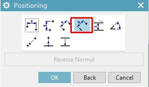
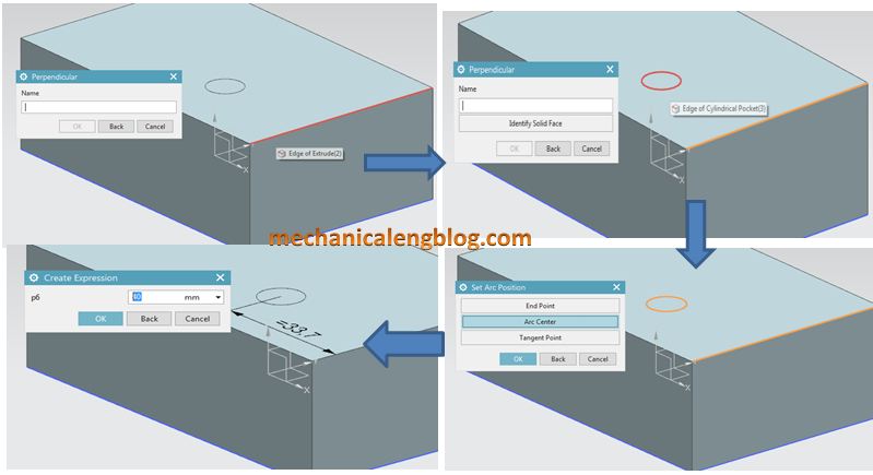
For this tutorial, I will select perpendicular option. In the graphics window, select edge of the box, then select edge of cylindrical pocket. In the set arc position dialog, select arc center option.
Type value you want in the create expression dialog, then click OK.
II. Create a rectangular pocket.
1. Select pocket command.
2. Select rectangular option in the pocket dialog.
3. Select solid face or datum plane option, then select object in the graphics window.
4. In the rectangular pocket dialog, type value of the pocket then click OK.
5. Use positioning dialog to precisely locate the pocket.
6. Click OK to complete.
III. Create a general pocket.
1. From the menu -> insert -> design feature -> pocket.
2. In the pocket dialog, select general option.
3. In the selection steps group, click placement face. Select the placement face in the graphics window.
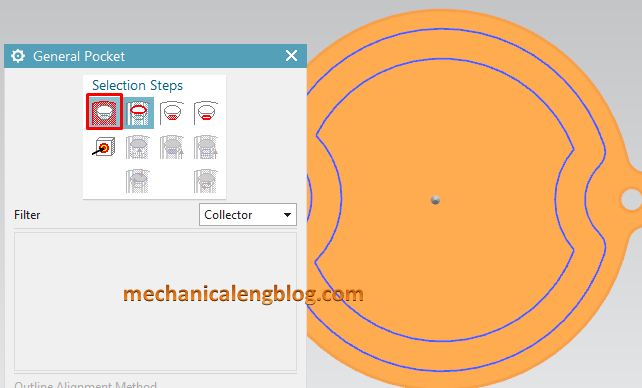
4. Click placement outline then select placement outline curves in the graphics window.
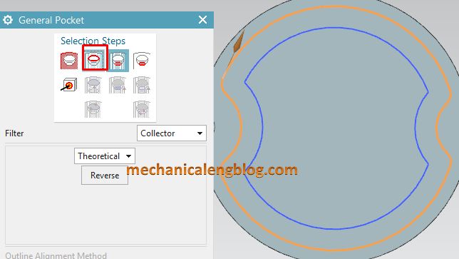
5. Click floor face then select the floor face in the graphics window.
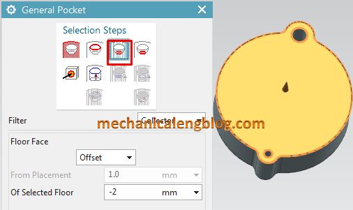
6. In the floor face group, select offset option, then type value in the of selected floor box. For this tutorial, I will select -2 mm.
7. Click floor outline in the general pocket dialog then select floor outline in the graphics window.
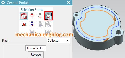
8. Click target body then select solid body in the graphics window.
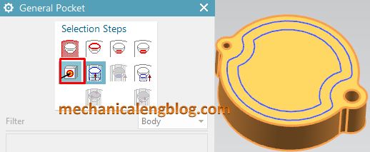
9. Click OK to complete.
CONCLUSION
We already finished this article. I hope you can know how to use pocket command in Siemens NX. There are three methods to create a cavity in an existing body: Cylindrical, Rectangular, General.
Thank for your reading?

Leave a Reply