Nx motion joints use to define constrained motions between motion bodies in the mechanism. Joint motion is always defined as the motion of the action body (the first link in the joint definition, also called i marker) relative to the base body (the second link, or j marker).
Where do I find it?
From the menu: Insert -> joint
Home tab: Mechanism group -> joint.
Siemens nx motion joint types and degrees of freedom constrained.
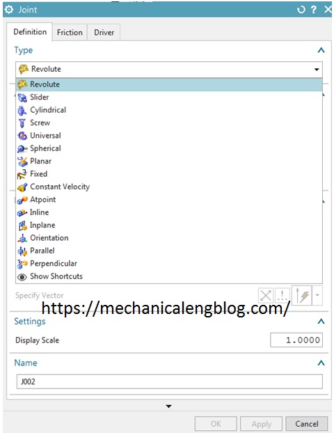
+ Revolute joint: A revolute joint connects two links. It has 1 degrees of freedom, one rotational degree of freedom about the Z-axis
+ Slider joint: A slider joint connects two links. It has 1 degrees of freedom, allowing one translational degree of freedom. Slider joints do not allow rotational movement between the two links
+ Cylindrical joint: A Cylindrical joint connects two links. It has two degrees of freedom a revolute and a Slider
+ Screw joint: With the RecurDyn solver, the screw joint removes five degrees of freedom. With Adams/Solver, the screw joint removes 1 degree of freedom.
+ Universal joint: A universal joint connects two revolving links. Universal joints used to create a flexible joint that allows two degrees of rotational freedom
+ Spherical joint: A spherical joint connects two links, allowing three rotational degrees of freedom
+ Planar joint: A planar joint connects two links, allowing three degrees of freedom between them: two translational and one rotational.
+ Fixed joint: A fixed joint connects a link to a fixed position or to another joint.
+ Constant velocity joint: A constant velocity (CV) joint is similar to a universal joint, except that a CV joint ensures a constant velocity through the joint’s spin axis. CV joints are common in the automotive industry as well as in certain types of machine design.
+ At Point joint: Constrains all 3 translational DOF
+ Inline joint: Constrains 2 transnational DOF
+ In plane joint: Constrains 1 translational DOF and constrains the translational motion of one link to the X-Y plane of another link.
+ Orientation joint: Constrains all 3 rotational DOF.
+ Parallel joint : Constrains 2 rotational DOF so the Z-axis of the action link stays parallel to the Z-axis of the base link.
+ Perpendicular joint: Constrains 1 rotational DOF on the action and base links to ensure that their Z-axes remain perpendicular.

Leave a Reply