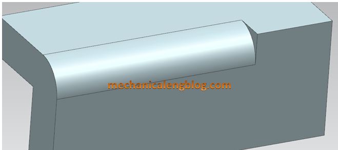
In the Siemens nx, edge blend command use to round sharp edges between faces. The radius can be constant or variable. This post will show how to create an edge blend with constraint radius, conic edge blend, an edge blend with variable radius, an edge blend with corner setback, and an edge blend with stop short of corner.
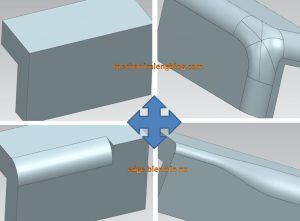
Where do I find it?
From the menu: Insert -> Detail feature -> edge blend.
From the home tab: Feature group -> Blend drop-down -> edge blend.
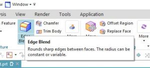
How to use edge blend command?
I. Create a circular edge blend with constraint radius.
1. On the feature toolbar, select edge blend.
2. In the graphics window, we will select the edge to blend.
3. In the edge to blend group, we will select circular from the shape list.
4. In the radius 1 box, type a value radius. In this example, the radius is 5 mm.
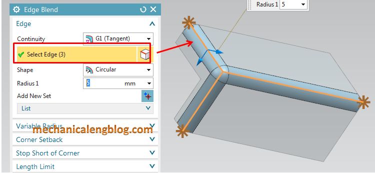
5. Click add new set to complete the selection of the first edge blend. Select edge option is active for second edge blend.
6. If you don’t want to create new edge blend, Click OK or apply to complete and don’t need click on add new set icon.
II. Create a conic edge blend.
1. Click the edge blend icon.
2. Select edge to blend in the graphics window.
3. In the shape type list, select conic option.
4. Select boundary and center in the conic method list.
5. Type value in the boundary radius 1 and center radius 1 box. For this example, I will type boundary radius 1 is 10 mm, center radius 1 is 4 mm.
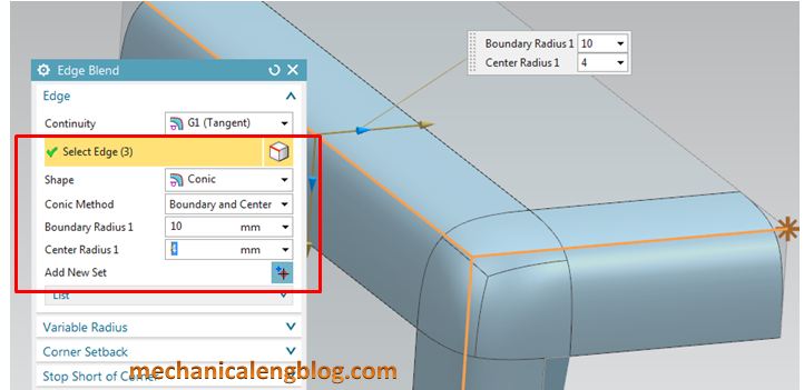
6. If you want to create second edge blend, click add new sheet icon and do from the step 2.
7. Click OK to complete.
III. Create an edge blend with variable radius.
1. Click the edge blend icon.
Note: If you don not see variable radius points option in the edge blend dialog, click on setting and select edge (more).
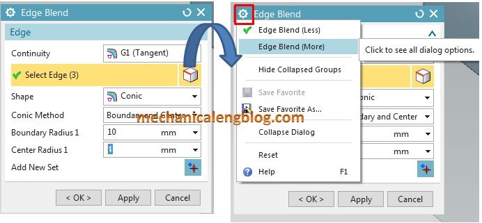
2. In the graphics window, we will select the edge to blend.
3. In the shape type list, select circular.
4. Click variable radius points group then click on specify new location.
5. In the graphics window, select specify points in the edge where you want to set a variable radius.
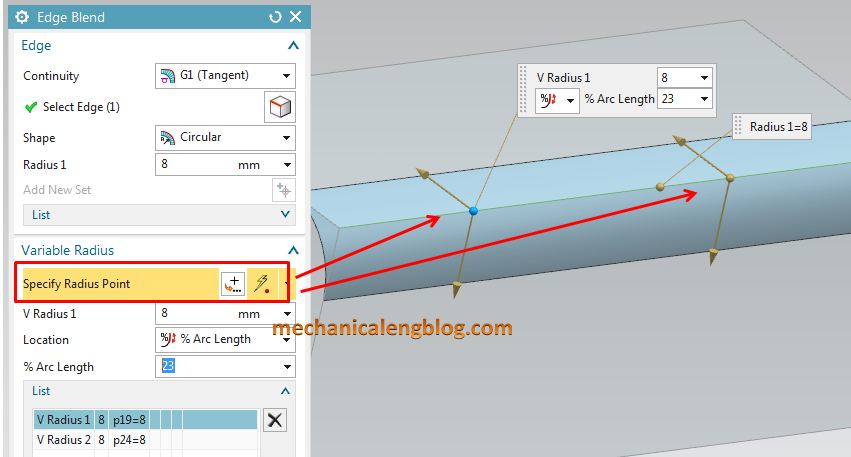
6. In the variable radius points group.
+ Click on V radius 1 to act it. Type radius value in the V radius 1 box. In this example, it is 4 mm.
+ You can change location of point with location option.
+ Click on V radius 2 to act it. Type a value in the V radius 2 box. In this example, it is 10 mm.
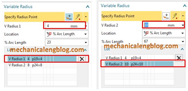
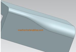
7. Click OK or apply to complete.
IV. Create an edge blend with corner setback.
This example will blend three edges.
1. Click the edge blend icon.
2. In the graphics window, select three edges to blend.
3. In the edge to blend group, select circular from the shape list.
4. Type radius value in the radius 1 box.
5. Click on the corner setback group the click on select end point. In the graphics window select specify point that is intersect of three edges.
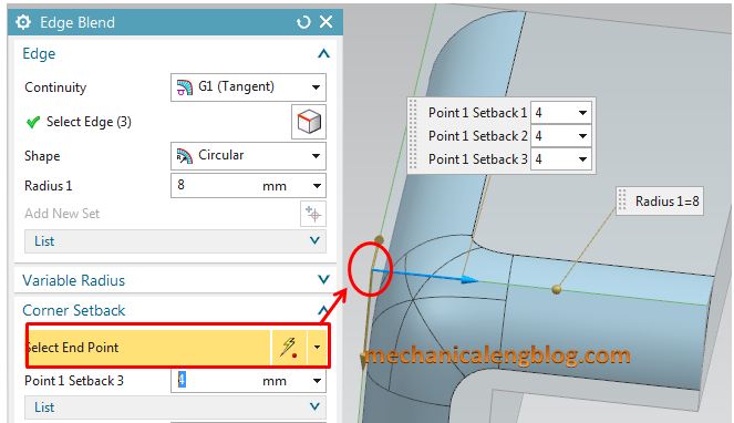
6. Click on the list to display setback points. Select each setback point and type value in the point setback box.
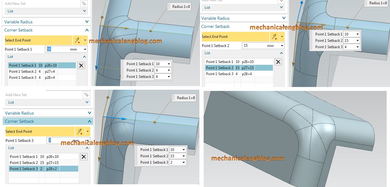
7. Click OK or apply to complete.
V. Create an edge blend with stop short of corner.
1. Click the edge blend icon.
2. In the graphics window, select edge to blend.
3. Select circular option in the shape list.
4. Type value in the radius 1 box.
5. In the stop short of corner group, click select end point and select and point on the edge where you want to stop the blend.
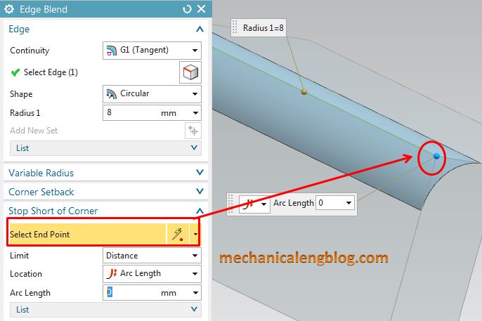
6. In the stopping location list, select at distance option.
In the location list, select arc length, then type length value in the arc length box. For this example, value is 20 mm.
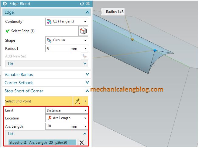
7. Click OK or apply to complete.
You can see this video below for more detail.

Leave a Reply