• Skip to main content
  • Skip to secondary menu
  • Skip to primary sidebar

Mechanicalengblog

siemens nx tutorial & injection molding technology

  • Plastic molding
  • Siemens nx
    • nx modeling
    • nx drafting
    • nx sketching
    • nx assembly
  • Mechanical basic
    • mechanical standard
  • microsoft office
    • microsoft word
  • About me
  • CONTACT ME
Home » Siemens nx » nx modeling » siemens nx circular blend curve command

siemens nx circular blend curve command

November 17, 2018 by mechanicaleng blog Leave a Comment

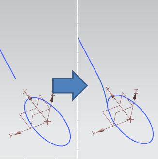
In the siemens nx circular blend curve command use to create a circular blend curve between two curve chains in the specified direction. In this tutorial, I will guide circular blend curve command.

siemens nx circular blend curve command

Where do I find it?

From the menu (top border bar): insert -> derived curve -> circular blend curve.

From curve tab: More gallery -> derived curve gallery -> circular blend curve.

siemens nx circular blend curve icon

How to use circular blend curve command?

1. From the menu: select insert -> derived curve -> circular blend curve.

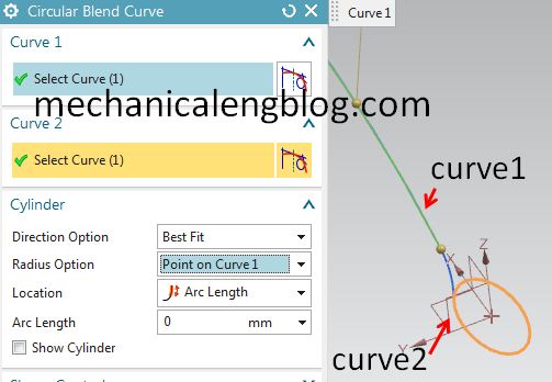
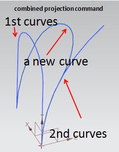
2. Select first curve chain in the graphics window then click on mid mouse button to change to 2nd curve chain.

3. In the graphics window, we will select second curve chain.

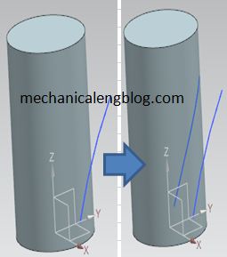
4. In the cylinder group, in the direction option, select best fit. In the radius option, select point on the curve 1. Select arc length for location. Input arc length in the arc length box. In this tutorial, I select value is 0.

siemens nx circular blend curve select curves

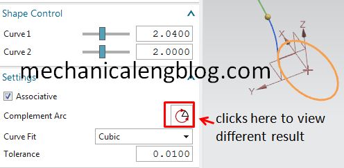
5. In the shape control group, press and drag to change shape control of curve 1 and curve 2.

6. In the setting group, select associative check box.

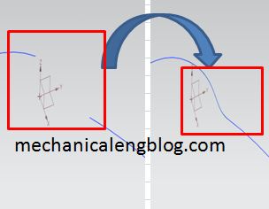
Clicks complement arc to change the result.

In the curve fit sub group, select cubic option.

siemens nx circular blend curve setting complement

7. Click OK or apply to complete.


Filed Under: nx modeling Tagged With: derived curve, nx modeling

Reader Interactions

Leave a Reply Cancel reply

Your email address will not be published. Required fields are marked *

Primary Sidebar

Recent Posts

  • connect multiple revolute, slider, cylindrical joints | nx motion
  • Create cable motion in Siemens nx
  • Siemens nx motion simulation create gear animation
  • nx motion create rack and Pinion animation
  • create Siemens nx motion simulation animation
  • Siemens nx sheet metal lofted flange command
  • Siemens nx sheet metal contour flange command
  • Siemens nx sheet metal flange command
  • What is oldham coupling | how it work
  • Siemens nx mirror feature command

Copyright © 2021 · Magazine Pro on Genesis Framework · WordPress · Log in