This post will explain the Siemens nx drafting dimensions definition as linear dimensions, chamfer dimensions, radial dimensions, angular dimensions, arc length dimensions, thickness dimensions.
I. Linear dimensions definition.
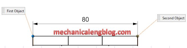
Linear dimension command used to create a linear dimension between two objects or points positions.
With linear dimension command, we can check horizontal dimension, vertical dimension, point to point dimension, perpendicular dimension, cylindrical dimension, hole callout?
Where do I find it?
From the menu (Top border bar): insert -> dimension -> linear.
From the home tab: Dimension group -> Linear.
How to write linear dimensions?
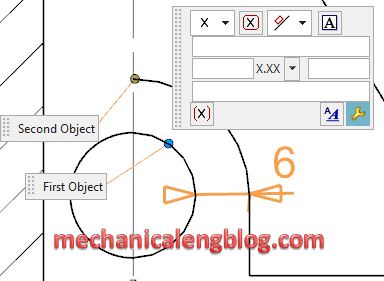
1. On the dimension toolbar, click linear dimension.
2. In the graphics window, select first object.
3. Select second object.
4. A dimension appears, drag and click to place the dimension to where you want.
5. Click Close or press ESC key to exit this function.
II. Chamfer dimensions definition.
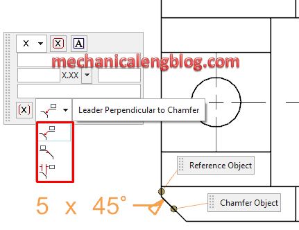
Chamfer dimension command used to create a chamfer dimension on a chamfer curve.
Where do I find it?
From the menu (top border bar): insert -> dimension -> chamfer.
From the home tab: dimension group -> chamfer.
How to write chamfer dimensions?
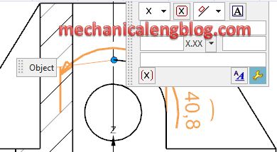
1. On the dimension toolbar, click chamfer command.
2. In the graphics window, select chamfer object.
3. Drag the chamfer dimension to where you want.
You can show chamfer dimension as leader perpendicular to chamfer, leader parallel to chamfer, or linear chamfer dimension.
4. Click close or press ESC key to complete.
III. Radial dimensions definition.
Radial dimension command used to create a radius or diameter dimension to a circular objects.
Where do I find it?
From the menu (Top border bar): Insert -> dimension -> radial.
From the home tab: dimension group -> radial.
How to write radial dimensions?
1. From the home tab, click radial dimension.
2. In the graphics window, click to select an arc, spline, or conic.
3. In the measurement group, you can select inferred, radial, diametral, hole callout option.
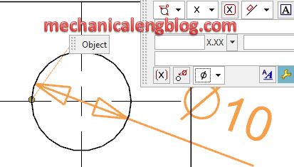
4. Drag the radial dimension to where you want.
Click close to exit this function.
IV. Angular dimensions definition.
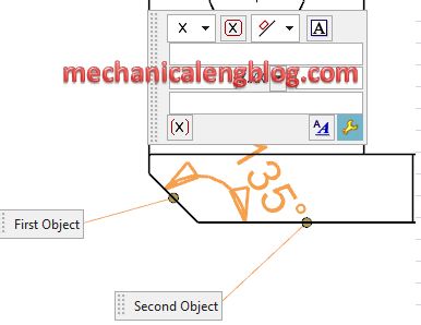
Angular dimension command used to create an angular dimension between two non-parallel lines.
Where do I find it?
From the menu (top border bar): insert -> dimension -> angular.
From the home tab: Dimension group -> angular.
How to write angular dimensions?
1. On the home tab, click angular icon.
2. In the references group, selection mode list, we will select objects. In the graphics window, select first object, and select second object.
3. In the measurement group, click the alternate angle to major or mirror angle.
4. Drag the angular dimension to where you want.
5. Click Close to exit this function.
V. Arc length dimensions definition.
Arc length command used to create an arc length dimension which measures the distance around the arc’s perimeter.
Where do I find it?
From the menu (Top border bar): insert -> dimension -> arc length.
From the home tab: dimension group -> arc length.
How to write and arc length dimensions?
1. On the toolbar, click arc length command.
2. In the graphics window, select the arc to dimension.
3. Drag and click to place dimension.
4. Click close to edit this function.
VI. Thickness dimensions definition.
Thickness dimension command used to create a thickness dimension which measures distance between two curves.
Where do I find it?
From the menu (Top border bar): insert -> dimension -> thickness.
From the home tab: dimension group -> thickness.
How to write thickness dimensions?
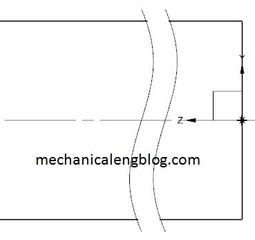
1. On the dimension toolbar, click thickness icon.
2. In the graphics window, select first objects then select the second object.
3. Drag the dimension to where you want then click to place the dimension.
4. Click close to exit this function.
VII. Ordinate dimensions definition.
Ordinate dimension used to create an ordinate dimension which measures the distance from a common point to a position on an object along an ordinate base line.
This post is following ordinate dimension.

Leave a Reply