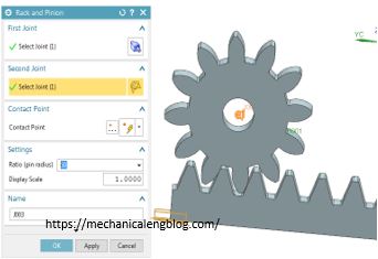
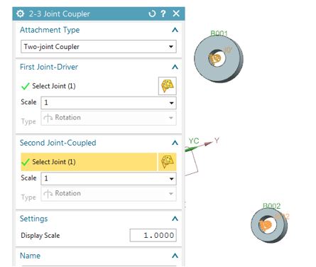
In Siemens nx motion simulation, A Rack and Pinion defines the relative motion between a slider joint and a revolute joint. You can use the rack and pinion couple to represent other types of mechanisms as Chain and sprocket, Timing belt and pulley, V-belt and sheave.
You can select any slider joint and any resolute joint as long as the axis of rotation of one is not parallel to the axis of translation of the other.
Where do I find it?
menu: Insert -> coupler -> rack and pinion.
Home tab: Coupler group -> joint coupler drop-down -> rack and pinion.
How to create rack and pinion animation in nx motion?
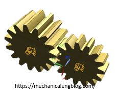
As the define, to use rack and pinion joint, you have to have 1 slider joint and 1 revolute joint. For this tutorial I will make rack and pinion animation like this picture below.

1. Define motion body for rack and pinion.
2. Take a joint for rack and pinion. Pinion -> revolute joint. Rack -> Slide.
3. Click rack and pinion icon.

In the graphic window, select the slide and revolute joint.
In the settings group, set the ratio between rack and pinion.
4. Click OK to finish rack and pinion joint.
5. See the mechanism animation.
+ From the results tab, click the play button to see animation,
+ From analysis tab, click animation button, click play to see animation. In the setting group, you can change animation delay and play mode.
You can see these video below for more detail.
NX 10 version.


Leave a Reply