This tutorial will explain how to add new component to an assembly and constraint between components in a nx assembly drawing.
I. General assembly concepts.
There are two concepts to creating an assembly structure.
+ Top-down modeling: Create component parts at the assembly level.
+ Bottom-up modeling: Create individual models in isolation, then later add them to assemblies.
II. How to add new component to an assembly.
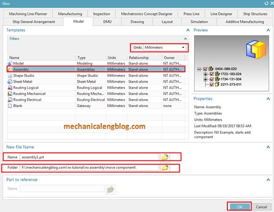
1. Create new assembly drawing. From menu -> new -> model -> assembly.
In the units list, select millimeters, in the new file name group, we will select new name and folder to save assembly file. Click OK .
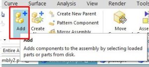
2. From the main menu: assemblies -> components -> add existing or on the assemblies toolbar, click add component.
3. If you want to see a preview of the component, do both of the following:
+ Select file -> preferences -> assemblies -> select preview component on the add check box in assemblies preferences dialog.
+ Select preview check box in the add component dialog.
4. In the add component dialog, select part is active. Select one or more parts that you want to add. You can select new part by:
+ Left click on new part in graphics window.
+ Click new parts in The loaded parts or recent parts list box
+ The assembly navigator.
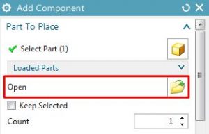
+ In the add component dialog, open group, click on open icon to open new part.
For this tutorial, i will add new parts by click open icon in the load parts group of add component dialog then select parts location.
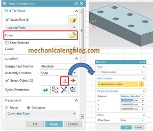
5. In the location group, select specify the positioning list you can select:
+ Absolute origin: Place the added components at absolute 0,0,0.
+ Select origin: Place the added components at a selected point.
+ By constraints: Place the assed components after you define their assembly constraints with other objects.
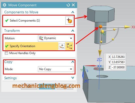
+ Move: Place the added components after you define how they should be positioned.
For this tutorial, I will select absolute origin option.
6. In the setting group, specify a name if you want your add part to have a different part name than the original part name. If you select multiple parts, this option is not available.
7. Click OK to complete this function.
III. Assembly constraints.
After you click OK, the assembly constraints dialog will appear.
In the type group, you can select constraint types:
+ Touch align: constraint two components so they touch or align with each other. This is the most common constraint.
+ Concentric: Constraint circular or elliptical edges of two components , centers line are coincident.
+ Distance: Minimum 3D distance between two objects.
+ Fix: Fix a part at its current position.
+ Parallel: vectors of two objects are parallel.
+ Perpendicular:

Leave a Reply