In the Siemens nx drafting, section view command use to create a section view from any parent drawing view. This tutorial will guide create a simple, step, revolved, and half section view.
Where do I find it?
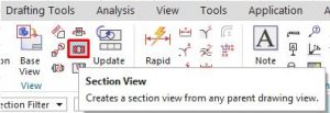
From the menu: insert -> view -> section view.
From the home tab: View group -> section view.
Right click on border of the parent view then select the add section view option.
I. Creating a simple section view.
1. Right-click the border of the parent view and choose add section view.
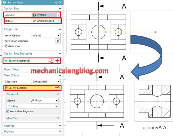
2. In the section view dialog, in the section line group. You can definition as dynamic: allows for the specification of dynamic section lines. Or select existing: allows for the section of an existing stand-alone section line.
In the method list, you can select simple, half, revolved, or point to point.
For this tutorial, I will select dynamic and simple option.
3. Left-click on specify locations in the section line segments group then select the cut position in the graphics window. Move the section view to new position.
4. Click on middle mouse or press Esc key to exit the function.
II. Create step section view.
This tutorial will guide to create a stepped section view that cuts through three holes in the part.
1. Right-click the parent view border and select add section view.
2. In the section view dialog, section line group, we will select dynamic and simple/stepped option.
3. In the graphics window, we will select center point of first hole. Click on specify location in the section line segments group then select second, third center points.
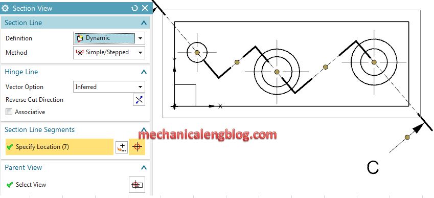
4. Click on specify location in the view origin group then select a location where you want.
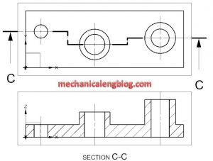
5. Press Esc key to exit the function.
III. Creating a revolved section view.
You can create a section views which are revolved about a common axis. A revolved section view can contain a single revolved cut plane, or contain steps to from multiple cut plane.
1. Right-click the parent view border and select add section view.
2. In the section view dialog, section line group, select dynamic, and the method list, we will select revolved option.
3. In the graphics window, we will select the rotation point for a revolved section line. Then select specify leg 1 location, then select leg 2 location. Click point constructor in the specify leg 2 location then select new location point.
4. Click specify location in the view origin group then select a location where you want.
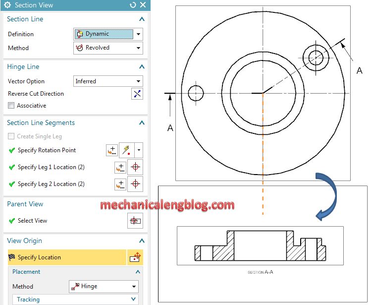
5. Press Esc key to exit this function.
IV. Create a half section view.
1. Right-click the parent view border when select add section view.
2. In the section line group, select dynamic and half option.
3. In the graphics window, create a section line segments by click to select the center arc to define the cut position, then select second point.
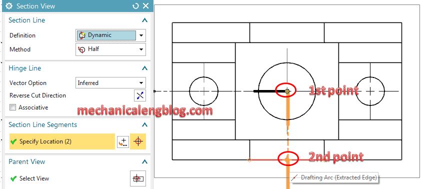
4. More your mouse to select new location where you want to save new section view.
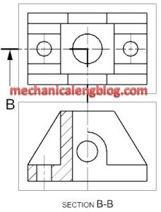
5. Press Esc key to exit this function.
Hello,
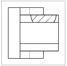
I’m doing some project for my school and i want to make a section view with a nerve in it.
The problem is when you do the section, the program does not detect the nerve, previously done with the nerve option. I’ve been looking through options and the only solution i’ve found is to extrude the nerve as another body, and then in the “not section” option choose the second body extruded. But I think there’s got to be another way to do it correctly.
Could you plese help me, or at least tell me if this could be done?
Thank you
Can you show it with picture, I can check it